It may require more than one train occupying a tunnel between two fan plants in order to achieve the design train throughput (trains per hour). During a train fire, smoke may affect non-incident trains in the same tunnel. Ventilation concepts were developed to prevent smoke from encroaching non-incident trains, but without sacrificing the ability to have more than one train occupying the tunnel between two fan plants.
Tunnel Linear Ventilation Duct Concept
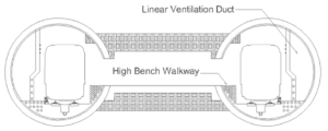
The smoke control is achieved by sub-dividing the tunnel into two or three ventilation zones. This sub-division is accomplished by using the trainway fans and the tunnel duct exhaust fans, housed in common fan plants, in combination with the linear ventilation duct as shown in Figure 1.

Figure 1: Tunnel Cross Section Showing a Linear Ventilation Duct
In the tunnel between fan plants #1 and #2 in Figure 2, the linear duct in each bore extends from both fan plants to the approximate one-third points of the tunnel section, which creates three ventilation zones within that section of tunnel. The train control system is designed to limit to no more than one train in a ventilation zone at any given time. Tunnel dampers along the tunnel are not required. This eliminates the maintenance issues of dampers. This tunnel system configuration is shown schematically in Figure 2.

Figure 2: Ventilation Zone Scheme
When an incident occurs in a tunnel, the ventilation zone occupied by the incident train will be identified by the signal system track circuits. The location of the incident car within the train consist will be reported to central control by the train crew, as is the case currently.
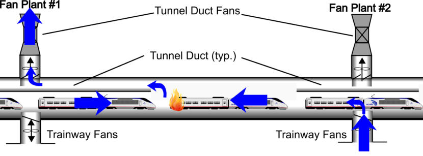
Once the direction of evacuation is determined, the appropriate combination of fans and dampers will be activated by personnel at central control through pre-programmed emergency operating modes to provide fresh air to passengers in the evacuation path to the tunnel cross passageways. Figure 3 provides a typical schematic illustration of a fire scenario that may be encountered in the tunnel and the respective fan operations.

Figure 3: Fire Scenario
More Ventilation Concepts
There are more potential ventilation schemes that could achieve one train per vent zone. For example:
- Air duct with dampers along the tunnel. During a train fire, two dampers at a spacing of about 400 feet near the fire will be opened for extracting smoke and hot gases from the fire car, and prevent smoke affecting non-incident trains on both sides of the incident train. This ventilation concepts could allow more than three trains between fan plants. The maintenance of dampers along the tunnel and the frequency of track outage could be an issue.
- CrossFlue fans between two tunnel bores. Fans are included in an enlarged cross-passage tunnel. Fans are operated in supply or exhaust to prevent smoke encroaching non-incident trains. Vent shafts to the outside ambient are not required.
The selection of feasible schemes depends on many factors, such as the number of trains allowed in the tunnel between two fan plants, the feasibility of adding a fan plant at the boundary between two vent zones, construction costs, maintenance, etc.
According to NFPA 130, the best protection to passengers and crew members is to allow no more than one train in a vent zone. For further information, please refer to the Post on “One Train Per Vent Zone“.
(featured images from Andrew Louie)

